Additional options
It describes additional functions available in the Topology menu.
Highlight filter
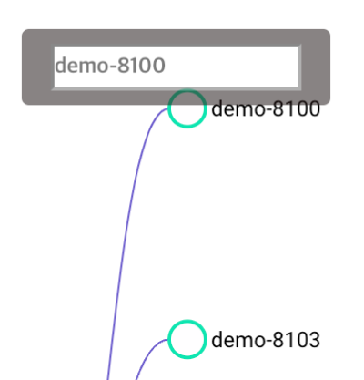
This function highlights the related nodes of a selected node. Complex relationships between numerous nodes can be easily verified with the topology.
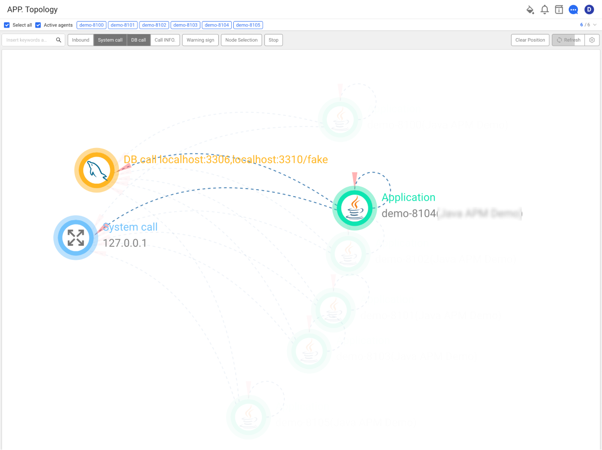
- Hover your mouse over a specific node to highlight the node, related nodes, and link data.
- Entry of the keyword allows you to keep the selection of the desired node. The highlighted state is kept even when the topology is updated.
Using the node selection function
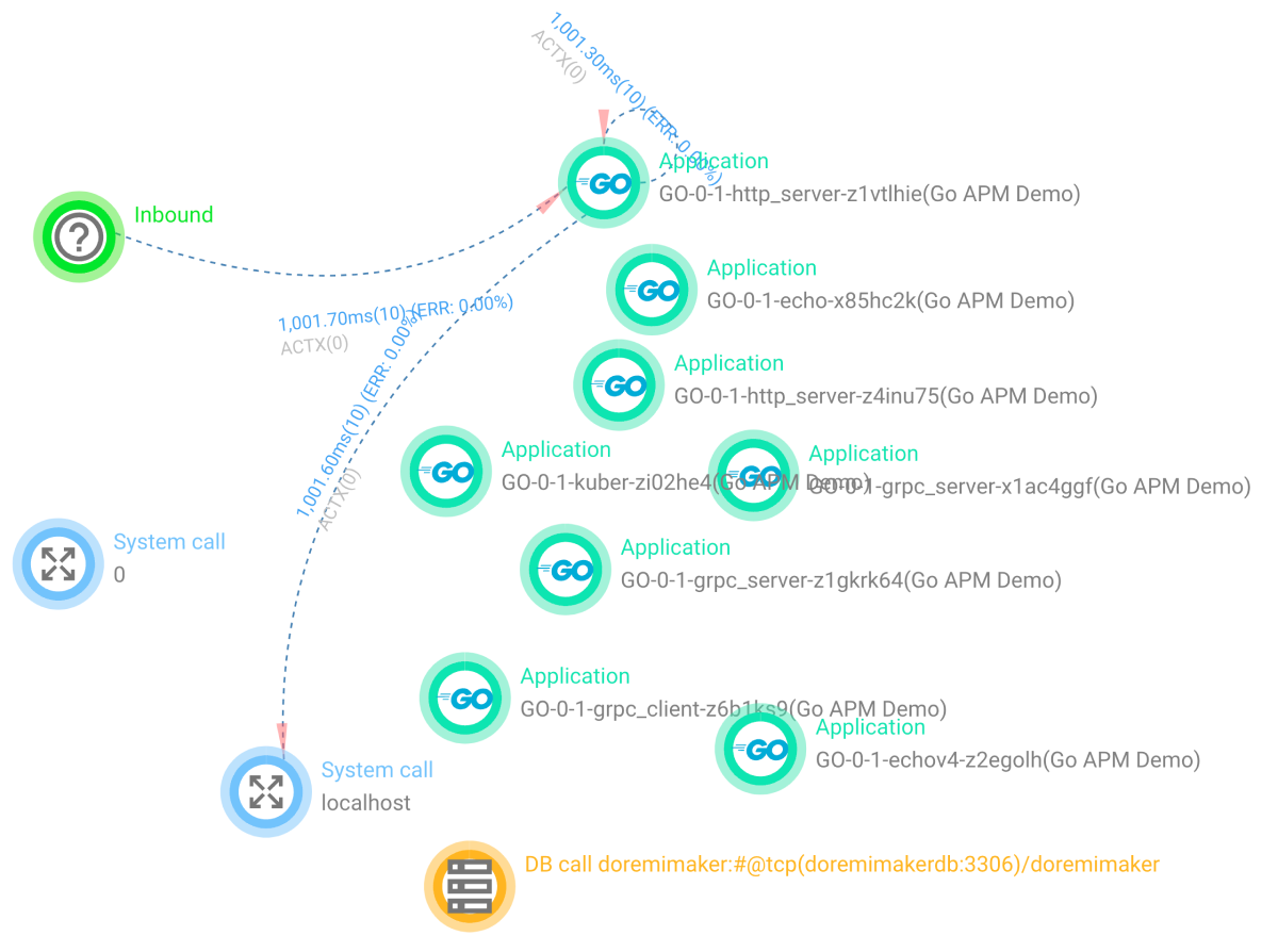
Select Node Selection. On the right of the screen, you can see the projects, DB calls, and outbound call nodes that are grouped on a diagram.
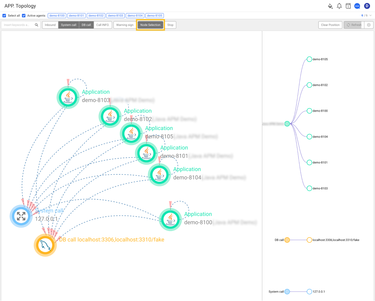
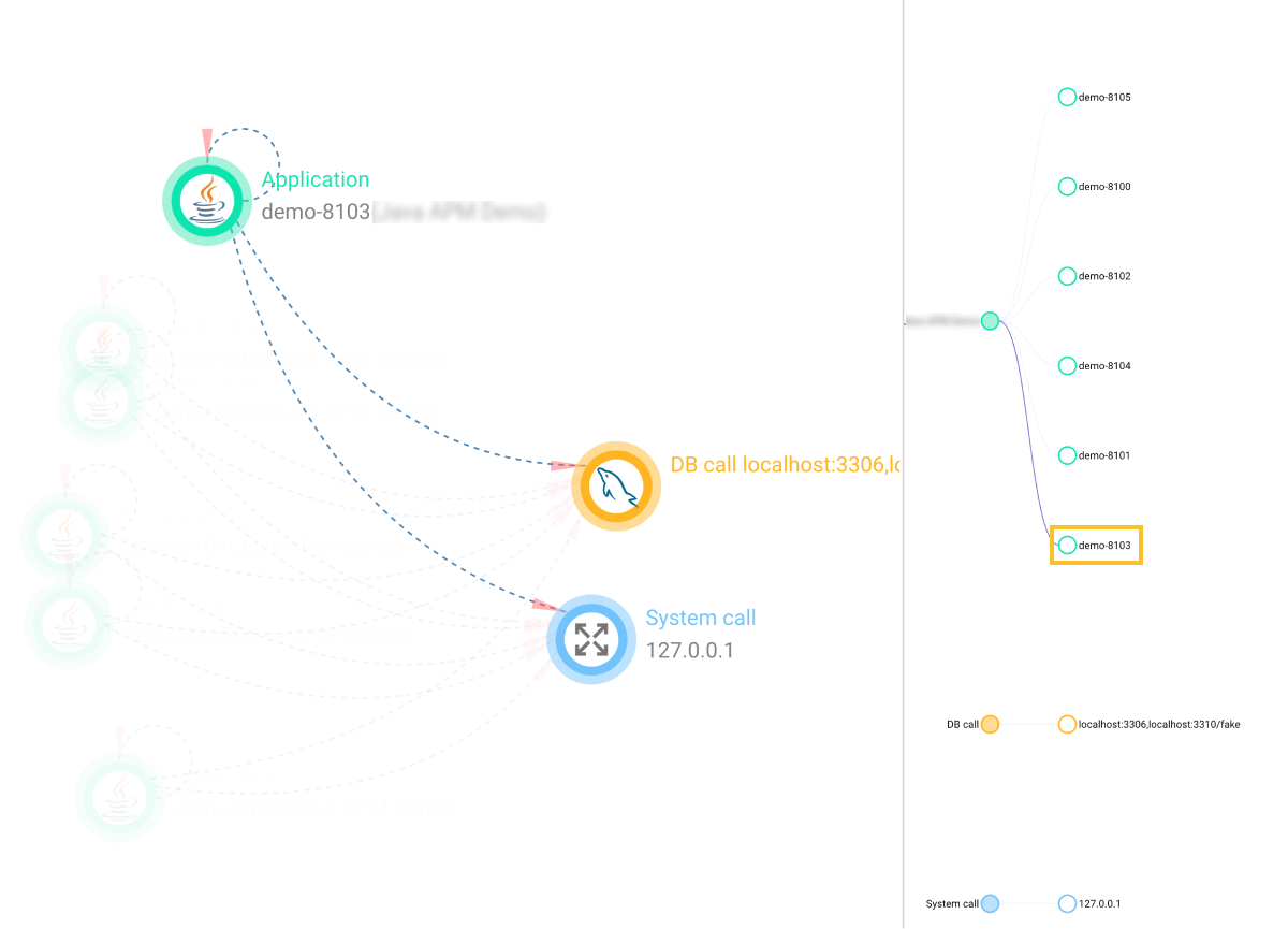
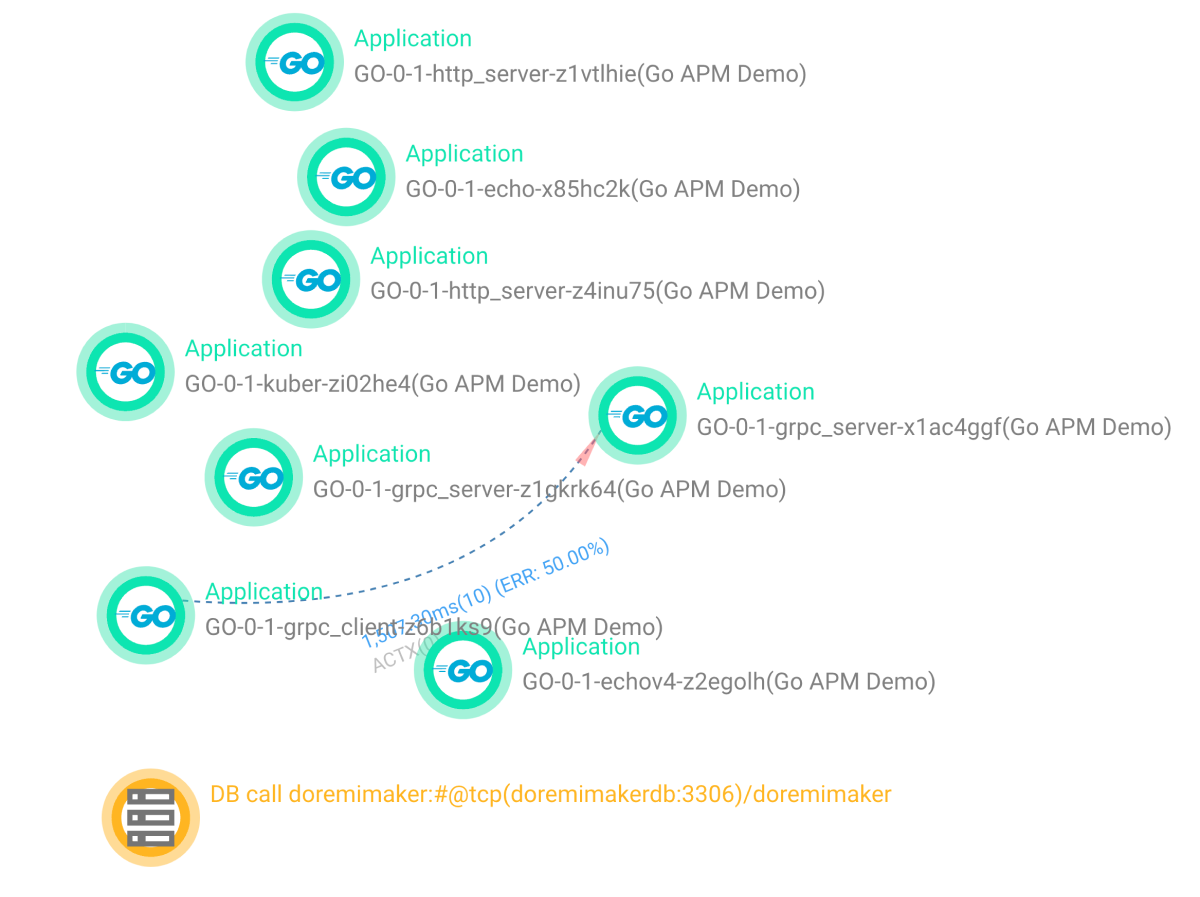
If you select a sub node in the diagram on the right, the highlight filter is applied to the node on the topology screen to the left.
On the screen to the right, you can use the following functions.
- Zoon In/Out
- Dragging
- Applying the highlight filter when clicking the subordinate node
- Hiding or displaying the subordinate node when clicking the upper node
To cancel the highlight filtering, delete the agent name in the keyword field.
In Group Statistics Topology, the function is provided using the Node Selection(Double click) button on the lower right of the screen.
Context menus
Context menus appear when you right-click on a node in the topology. They provide the menus such as links to go to the application monitoring dashboard.
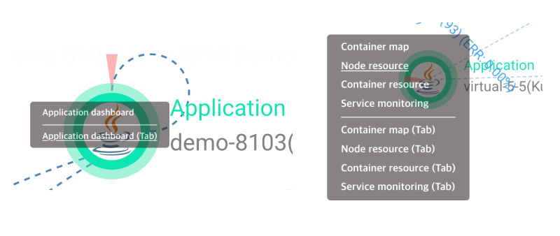
The menus such as Container Map, Node resource, and Container resource are available only in Container Monitoring.
Saving and restoring the node positions
On the topology, the position of a node in the chart can be changed by dragging with the left mouse button. The position of the changed node is maintained even if you enter another menu and then return to the topology screen.
- Save Position: The position of a changed node can be saved.
- Load Position: The position of a node is restored to the point when the position was saved.
- Clear Position: The node position is initialized.
- The node position menu may not be supported depending on the topology menu.
- The position data of the changed node is stored in the local storage of the web browser. The changed node position is not applied to the screens of other users.
Assigning and removing the alias
-
Select Node Selection.
-
Go to the node to alias on the right of the screen, and then right-click on it.
-
When the alias input field appears, enter the alias and then press Enter.
The alias data is saved. The alias saved at the time of retrieving the chart data is applied to the node on the topology screen.
The node alias data is saved to the local storage of the web browser.
Inbound / System call filters
By using the Inbound / System call button, you can change the visibility of external modules and outbound call nodes on the topology screen.
-
Inbound / System call visible status
-
Inbound / System call invisible status
Highlighting data above the threshold
When setting the call response times and error count thresholds between nodes, the nodes and call relationships that exceed the thresholds are highlighted. On the topology screen, select Warning sign. Enter the settings in Response time(ms) and Error count.
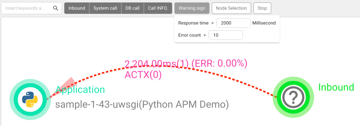
In Application topology, you can enter the following settings after selecting Warning sign.